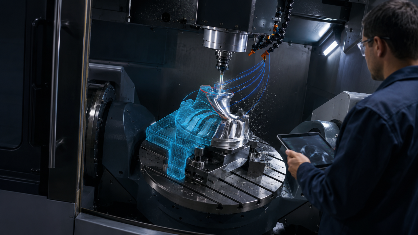
CAD/CAM is the integration of two classes of software: CAD creates a 3D model of a part, whilst CAM converts it into toolpaths and a control programme. The technician specifies the workpiece, tool, cutting parameters and coordinates, after which the system generates code for the CNC machine. Manually preparing a programme for a relatively simple part can take 4-8 hours, whereas with customised CAM templates, this process is often reduced to 1.5-3 hours.
Direct integration eliminates at least three types of errors: re-entering dimensions, working with an outdated version of the model, and incorrect transfer of geometry. Unlike a separate approach, CAD and CAM work with a single digital object. If the systems are not linked, the model is transferred via STEP or IGES, and parametric dependencies and the design history may be lost. The post-integration process comprises four main stages: creating a 3D model of the part in CAD, selecting machining operations and tools in CAM, calculating toolpaths and checking for collisions, and generating the control programme via a post-processor.
| Criterion | Separate CAD and CAM | Integrated CAD/CAM system |
| Model transfer | Export via STEP or IGES | Shared 3D model |
| Design changes | Re-import and verification | Recalculation of associated trajectories |
| Risk of errors | Manual entry and version confusion | Fewer manual operations |
| Preparation of a simple part | Approximately 4-8 hours | Approximately 1.5-3 hours |
| Model data | Potential loss of parameters | Links to geometry are retained |
Without CAD/CAM integration, data passes through several separate stages, and the risk of error increases at each one. The designer completes the 3D model, after which the production engineer transfers it to a separate CAM package via STEP or IGES. During such conversion, parametric links, the design history and some of the metadata may be lost. As we have already mentioned, for a simple part, the entire process of preparing the control programme often takes around 4-8 hours. The manual workflow looks like this:
The greatest delays occur following design changes. Even a minor adjustment to a hole or contour requires the model to be resubmitted, the toolpaths to be recalculated and the programme to be checked. An additional risk is working with an outdated file version, an incorrectly selected tool or incorrect cutting parameters.
Direct integration of CAD and CAM provides designers and production engineers with a shared working environment. Both specialists work with a single 3D model without the need for conversion to STEP or IGES. When the designer changes the dimensions of a part, the CAM software recognises the update and recalculates the associated toolpaths. This link is known as associativity. The integrated process comprises several sequential steps:
In a practical scenario, preparing the control programme for a new part prior to integration can take 6 hours, and around 1.5 hours once the process has been set up. To maintain the link between the 3D model and the machining preparation, GEO-MENTOR offers SOLIDWORKS CAM – an integrated module for CNC. It operates directly within the SOLIDWORKS environment, so the machining engineer can use the latest geometry without having to create a separate copy or convert via STEP or IGES. The machining engineer does not need to create a separate copy of the geometry, can respond more quickly to design changes, and maintains the link between the model, operations and toolpaths.
A modern CAD/CAM system covers the main operations – from drilling simple holes to machining complex 3D surfaces. The machinist selects a strategy based on the part’s geometry, the number of set-ups and the kinematics of the machinery. For flat body parts, 2.5D machining is often sufficient, whilst blades, impellers and moulds require multi-axis machining. A typical set of operations includes:
For parts with straight walls, holes and pockets, 2.5D machining usually covers the main tasks. Five axes are required when the tool needs to change its angle of inclination or machine multiple surfaces without re-setting. For such processes, GEO-MENTOR offers Dassault Systèmes solutions for manufacturing enterprises. These integrate the 3D model, machining operations, simulation and programme preparation, simplifying work with complex parts and various types of equipment.
CAD/CAM integration proves most valuable where production regularly repeats similar operations. If a single part is produced in several variants, associativity helps to quickly update toolpaths following changes to the 3D model. This is also important for complex surfaces where 3D or 5-axis machining is used, and where each CNC machine requires a precisely prepared control programme. The feasibility of integration should be assessed based on several criteria:
For simple, one-off parts, the impact may be less significant. For example, manually preparing a short programme sometimes takes less time than fully configuring a CAM project. To select a solution without unnecessary features, we analyse the type of parts, equipment and the repeatability of operations. Take a look at the sectors where GEO-MENTOR implements CAD/CAM; this will help you quickly and conveniently compare the system’s capabilities with real-world tasks in mechanical engineering, aerospace and other manufacturing sectors.
CAD/CAM integration eliminates the manual disconnect between design and manufacturing and combines these stages into a single digital process. The 3D model created in CAD becomes the direct source for constructing toolpaths and generating the control programme. As a result, the CNC machine receives up-to-date data without the need to re-enter dimensions or perform additional geometry conversion. This approach reduces production set-up time, simplifies the process of making changes and minimises the risk of errors during the transfer of information from the designer to the production engineer.
CAD is a system for design (3D models, drawings). CAM is a system for production preparation: it takes a 3D model from CAD and automatically generates toolpaths and a control programme for the CNC machine. CAD/CAM is either a single integrated solution (for example, SOLIDWORKS + SOLIDWORKS CAM) or a combination of two systems linked via a neutral data exchange format.
To some extent. Most CAM systems support importing via neutral formats (STEP, IGES, Parasolid). However, this results in a loss of associativity: if a designer changes the dimensions of a part in CAD, the production engineer will have to manually update the CAM model. Direct integration (for example, SOLIDWORKS CAM within the SOLIDWORKS environment) eliminates this problem – changes to the model are automatically reflected in the CAM without the need for re-importing.
Modern CAD/CAM systems support post-processors for most popular CNC machine tools: Fanuc, Siemens 840D, Heidenhain and Mitsubishi. The post-processor defines the G-code format and commands specific to a particular machine tool. In SOLIDWORKS CAM, post-processors for leading machine tool manufacturers are included as standard; additional ones can be ordered from the supplier after checking compatibility with a specific machine model.
A technician with experience of working on CNC machines can master the basic skills of 2.5D milling in a CAM system within 3-5 days of training. More complex strategies – such as 3D surface machining and 5-axis machining – require an additional week. If the CAM system is integrated into a familiar CAD environment (such as SOLIDWORKS CAM), the adaptation time is reduced, as the interface and operating logic of the system are already familiar.
It is suitable for both. Modern CAD/CAM systems support turning operations: roughing and finishing, grooving, thread cutting and boring. Some systems (notably SOLIDWORKS CAM) allow turning and milling operations to be combined in a single programme for turn-mill machining centres, which is particularly useful for complex parts such as bodies of revolution with pockets and holes.

