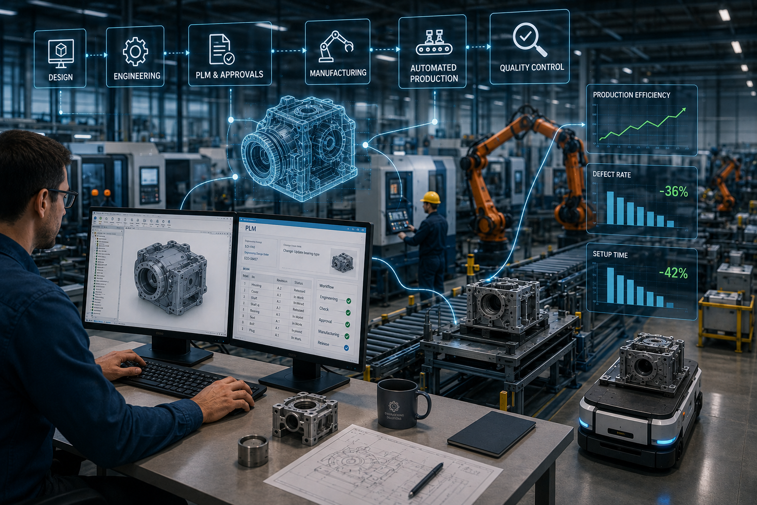
Industrial automation involves replacing manual and repetitive operations with programmable systems: from CNC machines and robotic workstations to fully automated production lines. It works not only with equipment but also with data: models, drawings, specifications, technical processes and approval workflows. Its effectiveness is usually assessed using three metrics: operation cycle time, defect rate and production set-up time. Unlike traditional mechanisation, production automation involves software control, version control and the exchange of information between stages.
CAD/PLM solutions form part of this process at the preparatory stage, even before a part is sent to the workshop. CAD helps to create an accurate 3D model, check the geometry, and prepare drawings and data for CAM/CNC. PLM manages the product lifecycle: versions, changes, BOM specifications, approvals and access rights for different departments. This enables the company to see which documentation is up to date, who made a change and when it can be released to production.
Automating production processes solely at the machine tool level speeds up the physical manufacture of a part, but does not solve the problem of data preparation. CNC machines, robots and automated lines operate faster when they receive an accurate model, an up-to-date drawing and a correctly prepared machining programme. If design documentation, calculations, BOM specifications and technical processes are still being coordinated manually, delays arise even before the part reaches the workshop. CAD/PLM covers precisely this preparatory stage: design, model verification, approval of changes and data transfer to the CNC machine. For example, without CAD/PLM, a change to a part’s design might take weeks to be sent back and forth by post between the designer, the process engineer and the production department, whereas with PLM, the approval process takes just a few days. The difference is clearly illustrated by a simple comparison.
| Approach | What is automated | Where the risk remains |
| Automation at the machine tool level | Machining, welding, assembly, repetitive operations on the shop floor | Errors in drawings, outdated versions, manual transfer of dimensions |
| CAD/CAM | 3D models, drawings, machining paths, preparation of NC programmes | Version control and cross-departmental approvals are required |
| CAD/PLM | Model, BOM, versions, changes, approval workflows, data transfer to production | Risk is reduced thanks to a single source of up-to-date data |
CAD/PLM delivers measurable benefits at those stages where engineering data is transferred from the designer to the process engineer, production and the quality control department. It is here that industrial automation ceases to be merely about machine tools and begins to work with models, specifications, versions and approval workflows. For example, if a company transitions from manual drafting to parametric 3D modelling, changing a single dimension automatically updates the associated elements of the model. For such tasks, GEO-MENTOR helps select SOLIDWORKS solutions for mechanical engineering when it is necessary to reduce part development time, minimise manual operations and prepare data for production without unnecessary file transfers. The benefits are best seen at specific stages:
When a company works with complex assemblies, multiple workshops or a long product lifecycle, a standalone CAD system is often no longer sufficient. A system is required that keeps track not only of the model, but also of changes, access rights, the BOM, approval workflows and inter-departmental communication. In such cases, it is worth considering Dassault Systèmes’ PLM and CAD solutions, so that production preparation does not depend on email correspondence, local copies or manually searching for the correct version of a document.
The benefits of CAD/PLM are most evident where a company works not with a single part, but with an entire system of changes, versions, drawings and approvals. In mechanical engineering, this quickly impacts production efficiency: the designer modifies the model, the production engineer sees the up-to-date data, and the workshop receives the correct documentation rather than a file named “final_new_2”. Most often, CAD/PLM delivers tangible results in the following situations:
If a company operates on a small-batch, one-off production basis, with few repetitive tasks and almost no complex approvals, the benefits may be less noticeable. In such cases, production optimisation often begins not with a full-scale PLM system, but with the organisation of CAD models, drawing templates and basic file storage rules. The key is not to implement a tool “just in case”, but to link it to a real problem: delays, errors, duplication of work or the loss of the latest version of a document.
The need for CAD/PLM should be assessed through a process audit. Look at how much time the team spends on drawings, approving changes, searching for the latest version and transferring data to the production floor. If production automation is already in place at the equipment level, but documentation is still being sent via email and spreadsheets, the bottleneck remains in the preparation stage. For an initial assessment and to improve processes, you can commission a technical service and CAD/PLM implementation from GEO-MENTOR. It is worth starting with a few questions:
Following such an audit, it is easier to understand what the company needs: 3D CAD, PDM or a full-fledged PLM system. For industrial companies, it is worth looking separately at industry-specific solutions for industrial automation, so that implementation can be linked to actual delays, errors and wasted time.
Industrial automation is most effective when it covers not only the production floor but also the preparatory stage: design, calculations, preparation of drawings and coordination of documentation. It is CAD/PLM solutions that help to reduce development time, minimise data errors and eliminate delays between the design department, process engineers and production.
No, CAD/PLM does not replace CNC machines, robots or production lines. These systems operate at a different level. CAD creates accurate models and documentation, whilst PLM manages versions, changes and approvals. Together, they provide the right data for the shop floor. As a result, industrial automation becomes more comprehensive: machinery carries out operations, and engineering data is not lost between departments.
The first step is to address the stage where the company loses the most time. If the problem lies with 2D drawings and manual modelling, start with 3D CAD. If files get lost between versions, you need PDM. If delays arise in approval workflows, changes, roles and access rights, it is worth planning for PLM. Production automation does not necessarily have to start with a large-scale system. Often, the right first step is a process audit.
The main sign is that there is more data than the team can safely manage on their own. For example, a single part has several revisions, drawings are approved via email, production engineers clarify the version over the phone, and the BOM is maintained in separate spreadsheets. In such a situation, automating production processes via PLM reduces the risk of errors thanks to a single data flow and speeds up approvals between departments.
Yes, CAD/PLM is not just suitable for traditional mechanical engineering. Mining, oil and gas, commercial and infrastructure projects also involve 3D models, specifications, changes, approvals and a long project lifecycle. In these sectors, it is important to access up-to-date documentation, track changes and maintain links between engineering solutions, procurement and the execution of works. This helps the team find the data they need more quickly, without the need for unnecessary clarification.
Yes, the preliminary impact can be assessed by auditing current losses. Record five metrics: time taken to prepare documentation, number of drawing revisions, time taken to approve changes, number of manual data transfers, and instances of working with out-of-date files. This will reveal where CAD/PLM can reduce delays. This approach is based on the specific circumstances of the organisation and helps to avoid unnecessary costs.

