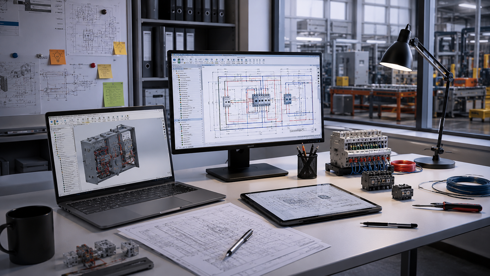
During the installation phase, an electrician spots an error in the wire numbering: the diagram shows one marking, whilst the documentation shows another. The team goes back to the files, checks the latest edits, and tries to find out who made the change and when; instead of controlling the process, the ECAD software effectively becomes the place where the error is duplicated in related documents. The cost of such an incident is reworked installation, delayed handover, additional materials, and hours of unnecessary communication between engineers, production, and procurement. This is no coincidence, but a typical systemic problem of non-parametric ECAD tools, where every change requires manual updating across all related documents.
In non-parametric ECAD, the electrical schematic often functions as a set of separate drawings and tables. An engineer changes a wire number, replaces a component or adjusts a connection, and then manually updates this data in the schematic, specifications, cabling documentation and BOM. For a manager, this is comparable to Excel without formulas: the table looks neat, but every value has to be recalculated manually. This is precisely why conventional CAD tools, AutoCAD-like solutions, or some outdated specialised systems create a risk of unnoticed discrepancies.
Parametric ECAD software operates on a different principle: data is interconnected, so a single change is automatically reflected throughout all documentation. If a wire, terminal or component changes, the system updates the associated schematics, reports, labelling and specifications without the need for manual duplication. SOLIDWORKS Electrical is built on precisely this approach – a solution for teams that need to control not only drawings but also the entire electrical logic of the project. It’s like Excel with formulas: you change one value, and the system automatically recalculates everything that depends on it.
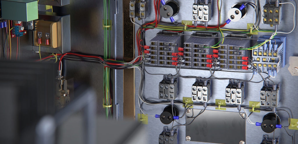
Changing a wire number in a non-parametric system seems like a minor issue only at first glance. An engineer changes the designation in one place, but then has to manually find all references in the schematics, cable tables, specifications, labelling and BOM. If even a single document remains unupdated, the installer is left with conflicting data: one number on the schematic, another in the table, and a third on the labelling. In such a situation, ECAD Software no longer helps to control the project, but forces the team to search for exactly where the change has “gone missing”.
Even a single such amendment can take 5-8 hours of work: approximately 1 hour is spent finding the discrepancy, another 2 hours on revising the documents, followed by re-checking, approval and communication with the installation team. If the error is found before production begins, the team wastes time. If it is spotted during the cabinet assembly, cabling or procurement stages, real costs are added to the working hours: reworked parts, excess cables, re-labelling and delayed delivery dates.
Traditional ECAD is often expensive not because of a single major error, but because of dozens of small manual actions that accumulate during the design process. When data is not linked, every copy, component replacement or parallel edit creates a risk of discrepancies in schematics, specifications and manufacturing documentation. It is at such moments that a non-parametric approach begins to affect not only the engineer’s work, but also deadlines, procurement and material costs.
Copying a finished schematic saves time only when the system automatically updates the linked data. In non-parametric software, it is easy to copy old wire numbers, obsolete components or previous errors along with the schematic, and then have to correct these manually in the specifications, wiring tables and BOM.
Replacing a single relay or terminal block can trigger a whole chain of manual corrections. If the ECAD software does not link the component to the schematic, labelling, reports and documentation, the engineer must manually check all instances where this part is mentioned and ensure none are missed.
When several engineers work on separate files without locking, version control or a single database, there is a risk of overwriting each other’s changes. One specialist updates the schematic, another changes the specification in parallel, and then the team spends time searching for the latest version and restoring the project logic.
The ROI from switching to parametric ECAD software is clearly evident not in presentations, but in the hours the team no longer spends manually reconciling schematics, BOMs and cable tables. Dassault Systèmes’ materials describe case studies where, following the implementation of SOLIDWORKS Electrical, companies reduced documentation preparation time, minimised errors in schematics and transferred data to production more quickly. For example, in the Shred-Tech case study, the generation of the electrical BOM was reduced from five days to approximately four hours, and the size of the electrical panels was reduced by 10%. This shows that savings arise not only at the design stage, but also in procurement, assembly and production control. The main results of the transition are most often seen in the following areas:
For managers, this means a more predictable budget: fewer emergency fixes, fewer re-checks and fewer situations where errors “pop up” during assembly. Therefore, the transition to SOLIDWORKS Electrical should be viewed not merely as the purchase of a new tool, but as a way to reduce the hidden costs of every engineering change.
Without ECAD-MCAD integration, electrical and mechanical engineers often work in parallel universes: one designs the circuit and cable connections, the other the enclosure, panel, fixings and installation space. As a result, the mechanical engineer may not see exactly where the electrical engineer has routed the cable, and the electrical engineer may not know if there is enough space for the actual route, bend radius and component placement. SOLIDWORKS Electrical 3D solves this problem through direct integration with SOLIDWORKS 3D CAD: cables, components, routes and the mechanical model all work within a single environment. The team can identify conflicts before production begins, rather than when the cabinet has already been assembled or parts have already been ordered.
When choosing ECAD software, it is worth looking beyond just the licence price. It is more important to understand whether the tool will help reduce manual edits, errors in documentation and material costs. Here is what to look for when choosing:
It is precisely against these criteria that modern solutions, such as SOLIDWORKS, should be assessed if a company plans to integrate electrical design with 3D models and manufacturing data. This is precisely what constitutes a practical approach to selecting a tool that should operate without the need for unnecessary manual checks.
The choice of ECAD software directly affects how much each error will cost: at the schematic, approval, procurement, assembly and production stages. GEO-MENTOR will help you assess your current electrical design process, identify areas where your team is wasting time and resources, and demonstrate how SOLIDWORKS Electrical can reduce manual edits, documentation discrepancies and the risk of rework. To understand whether the solution is right for your team, you can contact GEO-MENTOR for a consultation, task assessment and a demonstration of the system’s capabilities.
Parametric ECAD software works with data, not just graphics. If a wire number, component or connection changes, the system updates the associated schematics, tables, specifications and reports. In conventional 2D tools, such edits are often done manually. This increases the risk of discrepancies between the schematic, BOM and assembly documentation.
Not always. Companies often make the transition gradually: first transferring standard schematics, setting up component libraries, creating report templates and training the team. GEO-MENTOR can help assess which processes should be changed immediately and which are better adapted in stages.
Yes, especially if the team works with repetitive schematics, complex enclosures, cable routes and frequent changes. SOLIDWORKS Electrical helps reduce manual data duplication, align electrical and mechanical parts, and generate production documentation more quickly.

